M A S T E R P A G E
Teacher Background Reading
BuildingEngineering
4.1a
During an earthquake, a marked spot on the Earth might be seen to move erratically, tracing out a random path
resembling that of a wandering insect. “Ground motion” is a literal description, since the ground moves (generally
for a distance measured only in centimeters) relative to its starting point. The ground motion that is important in
determining the forces on a building is acceleration. As the seismic waves move through the ground, the ground
moves back and forth. Acceleration is the rate at which ground movement changes its speed.
Two other unit measures are directly related to acceleration. Velocity, measured in centimeters per second, refers
to the rate of the motion at a given instant. Displacement, measured in centimeters, refers to the distance an object
is moved from its resting position. If you move your hand back and forth rapidly in front of your face, it might
experience a displacement of 20 to 30 centimeters in one second and its acceleration and velocity may be quite
high, but no damage will be done because the mass of your hand is low. In a building with a mass in the thousands
of metric tons, tremendous forces are required to produce the same motion. These forces are transmitted
throughout the structure, so if the movement repeats for some minutes the building may shake to pieces.
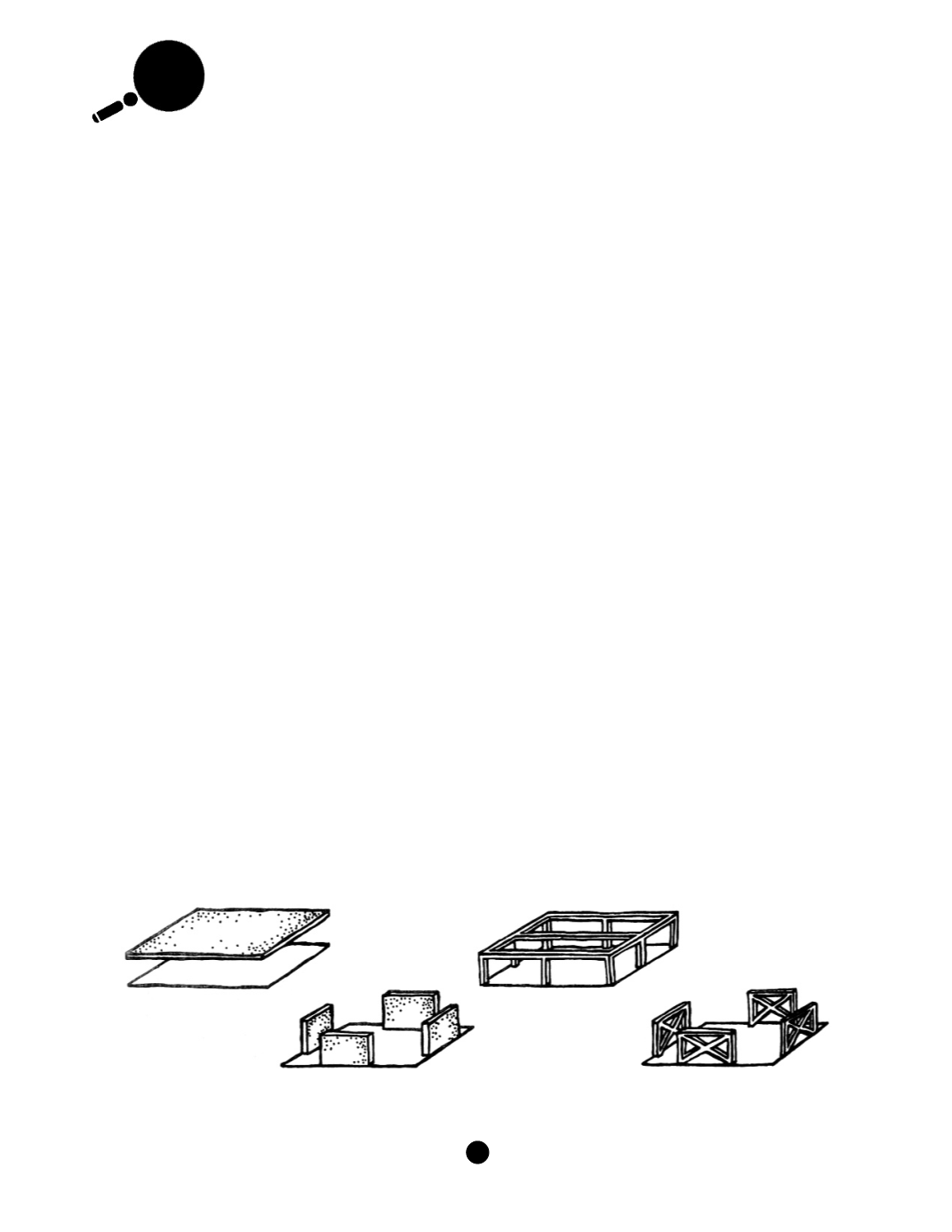
To overcome the effects of these forces, engineers rely on a small number of components that can be combined to
form a complete load path. In the vertical plane, three kinds of structural systems are used to resist lateral forces:
shear walls, braced frames, and moment-resistant or rigid frames. In the horizontal plane, diaphragms (generally
formed by the floor and roof planes of the building) or horizontal trusses are used. Diaphragms are designed to
receive lateral force between the vertical resistance elements (shear walls or frames). Shear walls are solid walls
designed to carry the force to the vertical resistance system. In a simple building with shear walls at each end,
ground motion enters the building and moves the floor diaphragms. This movement is carried by the shear walls
and transmitted back down through the building to the foundation. Braced frames act in the same manner as shear
walls, but may not carry as much load depending on their design. Bracing generally takes the form of steel rolled
sections (I-beams), circular bar sections (rods), or tubes. Rigid frames rely on the capacity of joints to carry loads
from columns to beams. Because these joints are highly stressed during movement the details of their construction
are important. As a last-resort strategy, rigid frames use the energy absorption obtained by deformations of the
structure before it ultimately fails.
Architecturally, rigid frames offer a certain advantage over shear walls or braced frames because they tend to
provide structures that are much less obstructed internally than shear wall structures. This allows more freedom in
the design of accompanying architectural elements, such as openings, exterior walls, partitions, and ceilings, and
in the placement of building contents, such as furniture and loose equipment. Nevertheless, moment-resistant
frames require special construction and detailing and therefore, are more expensive than shear walls or braced
frames.
Note:
Adapted from FEMA 99, October
1990, Non-technical Explanation of the NEHRP Recommended Provisions.
Diaphragm
Moment Resistant
Frame
Shear Walls
Braced
Frame
A G U
/
F E M A
232
S
E I S M I C
S
L E U T H S


